Battery
The processing using femtosecond laser is initiated by non-linear absorption of the radiation within generation of free electrons by multi-photon ionization. The femtosecond laser provides distinct advantages: the non-thermal ablation and the absorption within transparent materials due to the ultra-short pulse duration and the high intensity. With these advantages, the femtosecond laser processing is applied to industry, material science, and medicine.
With the increase of electrical vehicles and high-end portable electronics, the demand for lithium ion batteries with high power and energy densities is increasing steadily. The typical approaches to enhance the performances in the industry are thickening electrodes and lowering porosity. However, thickness and density of electrodes are limited due to increase of internal resistances such as electronic and ionic resistances. In our laboratory, power and energy densities of thick and dense LIBs are improved by a laser structuring technique. Laser structuring is transforming the flat electrode film into three-dimensional microstructure by ablating the electrode materials using lasers.
An ultrashort pulse laser (Yb:KGW laser, wavelength = 1030 nm, pulse duration = 190 fs, maximum power = 6 W, repetition rate = 30 kHz) was used for laser structuring of NMC532 cathodes with thickness from 100 to 210 μm. As shown in Fig. 1, micro-grooves with a high uniformity in shape and size are produced by laser structuring. No evidence of melting or resolidification are found at the edge of laser-structured grooves as observed on these cross-sectional image.
Fig. 1 SEM images for (a) unstructured and (b) structured electrodes; (c) and (d) cross-section of each electrode (thickness = 210 μm)
As shown in Fig. 2(a), specific energy of the electrodes measured at 0.1 C increased with the increase of thickness. However, the specific energy of unstructured electrode dropped drastically as the current rate was increased beyond 0.1 C. The crossing of specific energy between the laser-structured and unstructured electrodes of the same thickness occurred at different current rate depending on thickness. For example, although the specific energy of the low-porosity laser-structured electrode of 210 μm thickness, “Low_S_210” in Fig. 2(a), was lower than that of the low-porosity unstructured electrode of the same thickness, “Low_U_210” in Fig. 2(a), at 0.1C due to mass loss, the specific energy of “Low_S_210” was higher than that of “High_U_210” for all other current rates above 0.1 C.
As shown in Fig. 2(b), rate capability of unstructured electrodes severely deteriorated with the increase of electrode thickness and current rate. Even the performance of laser-structured thick electrode (“Low_S_175”) was almost equal to that of the unstructured thin electrode (“Low_U_100”) up to 0.5 C. The gap of the rate capability between unstructured and structured electrodes was remarkable at high current rate. These results indicate that a simultaneous enhancement of energy density and power density at high current rate is possible by laser structuring of electrode, depending on the thickness.
Fig. 2 (a) specific energy and (b) rate capability of unstructured and structured electrodes depending on thickness and current rates (“Low_S_175” indicates a structured electrode with thickness of 175 μm and porosity of 26%)
The simultaneous enhancement of energy and power densities results from reduction of cell polarization and improvement of lithium-ion diffusion. As shown in Fig. 3, the grooves on the electrode surface produced by the laser structuring improve the ion kinetics by widening the electrode surface area and enlarging the activated volume of the electrode. The increased surface area by laser structuring of electrodes should have resulted in an enhancement of electrochemical reaction between the electrolyte and surface of bulk active material.
The results in this study showed that the drawbacks caused by thickness increase or porosity decrease in LIBs, such as power density drop and poor capacity usage, can be considerably compensated by expanded diffusion path of Li-ion through laser structuring. The power and energy densities of laser-structured electrode were simultaneously enhanced in advanced values than thickness and porosity applied in industry at the high current rate.
Fig. 3 Schematics of possible lithium-ion diffusion paths before and after laser structuring
Transparent materials
The absorption of light in a transparent material must be nonlinear because there are no allowed electronic transitions at the energy of the incident photon. For such nonlinear absorption to occur, the electric-field strength in the laser pulse must be approximately equal to the electric field that binds the valence electrons in the atoms. To achieve such electric-field strengths with a laser pulse, high intensities and tight focusing are required. In our laboratory, we study internal processing characteristics of quartz using femtosecond laser (pulse width of 250 fs, wavelength of 1030 nm, repetition rate of 10 kHz) and the application to control transmittance of the transparent materials. As shown in Fig. 4, a cavity having shape of cylinder is produced at the focal point when a laser beam is tightly focused in the quartz. The diameter and length of cavity increase with rising pulse energy and flat focusing position. At the higher pulse energy, the crack is generated surrounding the cavity.
Fig. 4 Microscope images of scattering pattern shape and size with regard to pulse energy and focusing position
A light is refracted, reflected and absorbed when the light reaches to the medium with different refractive index. As an application using this phenomenon, transmittance of transparent materials can be controlled by changing shape, size, pitch, depth and arrangement of scattering patterns. Figs. 5 shows the changed transmittance of quartz (thickness of 4mm) depending on laser processing conditions. As shown in Figs. 5(a) and (b), the change of transmittance with regard to the pulse energy is negligible. However, transmittance decreases by 10 %p by the tight focusing using a high magnitude lens. As shown in Fig. 5(c), transmittance is significantly depending on pitch of scattering patterns. The transmittance is gradually dropped with decrease of pitch, and the controllable transmittance range is from 90% to 46% at wavelength of 400 nm. The transmittance also can be controlled by the number of scattering patterned layers as shown in Fig. 5(d). The transmittance is considerably decreased by adding a scattering patterned layer. In particular, the more the pitch decreases, the more rapidly the transmittance is dropped. It is understood that changing the pitch is advantageous to drastically control the transmittance of transparent materials at the single layer or multi-layers. When the two layers are applied, arrangement (parallel or staggered) between two layers is a variable to control the transmittance. However, the arrangement of two layers is negligible to control the transmittance regardless of focusing condition and pitch as shown in Fig. 5(e). These results can be applied to the local transmittance control of transparent materials such as photomask for photolithography and optical components.
Fig. 5 Transmittance of quartz with regard to (a) pulse energy, (b) focusing condition, (c) pitch, (d) the number of layers, and (e) arrangement of layer.
Micro heat pipe
Heat generation in mobile electronic devices may reduce its life span, decrease operational stability, and even cause failure of the devices. Due to the compactness of modern mobile electronic devices, cooling devices also need to be small in size but highly effective in transporting heat. Micro heat pipe (MHP) is a solution to this problem.
A heat pipe consists of a sealed pipe or tube made of a material with high thermal conductivity such as metals (FIG. 1). Inside of the heat pipe is partially filled with working fluid like pure water or alcohol and maintained at a low pressure near vacuum. Heat pipe is typically divided into three sections, that is, the evaporator section, adiabatic section and condenser section. For cooling of a device, the evaporator section is brought in contact with the heat source so that the heat input into the evaporator section vaporizes the working fluid. The vapor is then flow to the condenser section due to pressure difference and there condenses back into liquid by removal of heat. Heat removal at the condenser section is mostly done with a cooling fan or secondary cooling water. The coolant at the condenser section returns to the evaporator section by capillary pressure produced by a wick structure, which completes the flow cycle of the working fluid.
Fig. 1 Schematic of a micro heat pipe
Unlike conventional heat pipes that use either wire mesh or sintered metal for the wick structure, it is difficult to adopt the same approach in MHPs as MHP size cannot be reduced below a certain limit, for instance, of 2?3 mm in thickness, due to the volume of the wick structure itself. Instead, fabrication of microgrooves on the heat pipe housing for the wick structure has been widely adopted as a means of minimizing the size of the heat pipe.
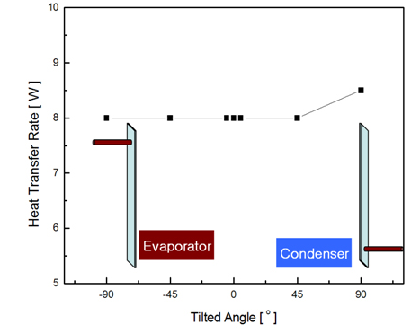
Heat transfer efficiency of a MHP depends significantly on the orientation of operation. Specifically, most MHPs do not function if the condenser section is toward the gravity direction, the adverse-gravity orientation, because in this case the capillary pressure should overcome the additional gravitational pressure. This is a critical issue for the application to mobile electronics such as PDA, cellphone, etc. because the orientation of these electronics during use can be randomly changed. Therefore, it is greatly desired to manufacture MHPs that produce a strong capillary pressure to overcome gravity effect and thus their performance becomes orientation free.
The capillary pressure (Pc) produced in a wick depends upon the surface tension (s) and capillary radius (rc) as follows

Thus, provided that the working fluid is predetermined, the capillary pressure and hence the cooling capacity of an MHP rely on the capillary radius. For the case of microgrooves, rc is a function of groove width (w), contact angle (a) at the liquid-solid interface, and the corner aperture angle (f) and for a triangular microgroove rc=w/cos(a+f). Since the contact angle depends on the surface tension of the working fluid and roughness of the wall, a microgroove with a sharp corner aperture angle and a narrow width is desired in order to achieve high capillary pressure.
The fabrication of narrow grooves of about 100 mm in size with a sharp corner angle is a challenging task for conventional micromachining techniques, while laser micromachining can be effectively applied for this purpose. Laser micromachining is a non-contact, single-step process that requires a simple system.
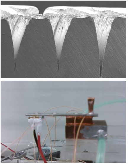
In our laboratory, we designed and fabricated fan-shaped microgrooves as the wick structure using femtosecond laser micromachining (FIG. 1). The fan-shaped microgrooves can induce a much greater capillary pressure than conventional triangular microgrooves of a similar size. Copper was chosen as the fabrication material in consideration of its good thermal conductivity. From experiments, it was demonstrated that the MHP based on fan-shape microgrooves of the size of 56 mm (L) ´ 8 mm (W) ´ 1.5 mm (H) has heat transport capacity as high as 13 W, and that this MHP functions under adverse-gravity conditions with little change in cooling capacity (FIG. 2), a key advantage for application in modern mobile electronics.

Fig. 1 Fan-shape microgrooves fabricated using femtosecond laser for high capillary pressure, top, and the experimental set up for the evaluation of heat transfer performance of the MHP, bottom

Fig. 2 Variation of heat transfer rate with respect to the tilt angle, showing orientation-free performance